
Translucency in OBJ / MTL Files
This post describes some reverse engineering work on the handling of translucency in MTL material files used with legacy OBJ 3D model files.
Motivation
Endlyss is a hybrid 3D modeling game inspired by Minecraft's creative mode. I like architecture and designing buildings. I really enjoy the building aspect of Minecraft (compared to using something like 3DS Max, or even SketchUp, which I find too hard to use to create buildings). However, I'm frustrated by the voxel limitations of MC. So I decided to make my own modeling game targeted at casual users but with power tools that would satisfy a 3D modeling artist. Endlyss is that game.
In order to bring data in and out of Endlyss I wrote support for both Minecraft and OBJ import and OBJ export. OBJ files specify the material name for each mesh, but the materials themselves are described separately in MTL files. Those are documented extensively online, e.g.,
http://www.fileformat.info/format/material/
http://paulbourke.net/dataformats/mtl/
However, the documentation is not all consistent, and in some cases does not match what I observe when importing files into 3DS Max (version 14.0, 2011). Compatibility with Max is the primary reason to have OBJ support, so that trumps the documentation.
Why use the legacy OBJ format instead of a full-featured file format with clear documentation? For example, COLLADA or FBX. Like many in the graphics community, I appreciate the features in the newer formats but find them hard to work with in practice. I prefer to use simpler, more widely-supported formats, and OBJ is something of the lowest common denominator for 3D models.
Transmission vs. Partial Coverage
MTL Files
Wavefront MTL files contain a series of blocks that look something like this for specifying materials:
newmtl default
Ns 10.0000
Ni 1.5000
d 1.0000
illum 2
Ka 1 1 1
Kd 1 1 1
Ks 0.0 0.0 0.0
Ke 0 0 0
map_Kd default.png
map_d alpha.png
I won't describe those in detail (see http://www.fileformat.info/format/material/), but essentially:
Post Script: What about Blender?
Blender seems to completely ignore "Tf" and uses the alpha channel of the map_Kd for alpha cutouts.
Motivation
Endlyss is a hybrid 3D modeling game inspired by Minecraft's creative mode. I like architecture and designing buildings. I really enjoy the building aspect of Minecraft (compared to using something like 3DS Max, or even SketchUp, which I find too hard to use to create buildings). However, I'm frustrated by the voxel limitations of MC. So I decided to make my own modeling game targeted at casual users but with power tools that would satisfy a 3D modeling artist. Endlyss is that game.
In order to bring data in and out of Endlyss I wrote support for both Minecraft and OBJ import and OBJ export. OBJ files specify the material name for each mesh, but the materials themselves are described separately in MTL files. Those are documented extensively online, e.g.,
http://www.fileformat.info/format/material/
http://paulbourke.net/dataformats/mtl/
However, the documentation is not all consistent, and in some cases does not match what I observe when importing files into 3DS Max (version 14.0, 2011). Compatibility with Max is the primary reason to have OBJ support, so that trumps the documentation.
Why use the legacy OBJ format instead of a full-featured file format with clear documentation? For example, COLLADA or FBX. Like many in the graphics community, I appreciate the features in the newer formats but find them hard to work with in practice. I prefer to use simpler, more widely-supported formats, and OBJ is something of the lowest common denominator for 3D models.
Transmission vs. Partial Coverage
You can read a discussion of the difference between transmission and partial coverage in the appendix of this paper: http://graphics.cs.williams.edu/papers/CSSM/. The basic idea is that partial coverage means "this surface has holes in it" and transmission means a combination of "light travels at a different speed through the medium on the other side of this surface" and "as it passes through that material, some, but not all light is absorbed." You can see some of the differences in the photograph below.
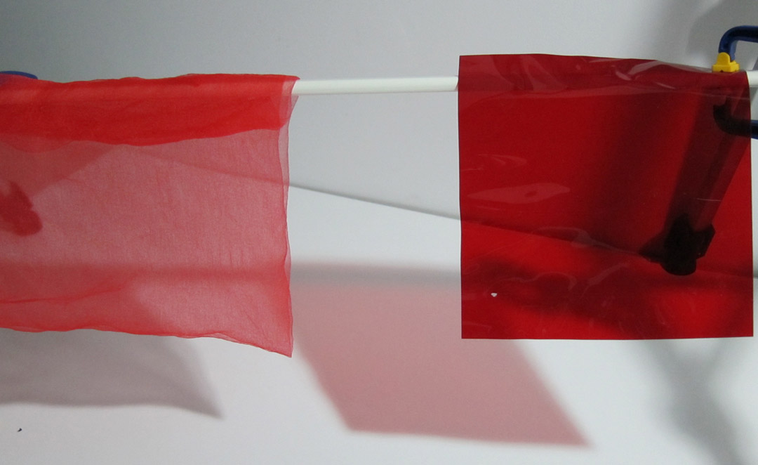 |
| Thin red cloth has 50% partial coverage, so it reflects 50% of "red" light. A red gel has 50% transmission, so it reflects almost no light but transmits 50% of the "red" light. |
In general, partial coverage is useful for representing cutouts (1 = solid, 0 = hole), and holes and edges below the resolution of the texture map (with fractional values). For example, the edges of leaves that cross through texels, and a window screen for keeping bugs out. Transmission creates refraction and "colors" the light that passes through it.
You also should see a diminished specular highlight on a surface with partial coverage (since that surface is partly not covered by the material!), but should see full-strength specular highlights on a transmissive surface--although you should set your constants to ensure energy conservation.
You also should see a diminished specular highlight on a surface with partial coverage (since that surface is partly not covered by the material!), but should see full-strength specular highlights on a transmissive surface--although you should set your constants to ensure energy conservation.
Do we really need both transmissive and partial coverage constants? Well, it is possible to represent frequency-invariant (i.e., uncolored), non-refractive transmission using partial coverage. It is possible to represent partial coverage for materials with no specular reflection (which are themselves impossible, since anything that transmits must reflect due to Fresnel effects) using transmission and no refraction. But those are pretty severe and confusing limitations for a physically-based renderer, so I prefer to keep the concepts separate.
MTL Files
Wavefront MTL files contain a series of blocks that look something like this for specifying materials:
newmtl default
Ns 10.0000
Ni 1.5000
d 1.0000
illum 2
Ka 1 1 1
Kd 1 1 1
Ks 0.0 0.0 0.0
Ke 0 0 0
map_Kd default.png
map_d alpha.png
I won't describe those in detail (see http://www.fileformat.info/format/material/), but essentially:
- "illum" specifies the kind of BSDF by number
- "K" values are RGB parameters
- "map" values are texture map parameters that trump the associated "k"
- "N" values are scalar parameters
There are several parameters in these blocks that affect the transmission of light and partial coverage of a surface. Based on my experiments with 3DS Max, these are:
- "d" specifies a scalar transmission value, where 1 = no transmission and 0 = 100% transmission. This must be transmission and not partial coverage because if d=0, then you can see specular highlights.
- "map_d" is a grayscale image that specifies a varying "d" value across a surface.
- "Tf" is an RGB value, but 3DS Max 2012 averages across the three channels to produce a scalar transmission coefficient. Specifically, 3DS Max transmits (1.0 - Tf) of the light, which is the opposite of what the above reverse-engineered documentation says. For example, 'Tf=1 1 1" transmits no light and "Tf=0 0 0" transmits all background light.
- The alpha channel of the "map_Kd" texture is ignored.
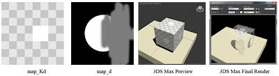
Here's a sample of one test that I ran to determine that "d" is transmission and not partial coverage:
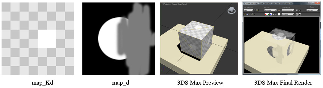
The map_Kd texture map is in RGBA8 PNG format. The white square in the map_Kd has A=0, which you can see is ignored in the render on the far right. The specular highlight on the d=0 part of the map in the right image shows that this is a transmissive coefficient and not partial coverage.
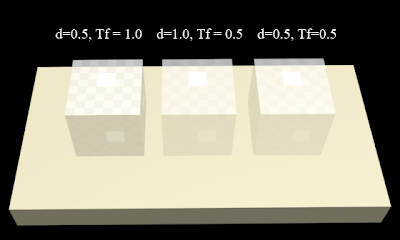
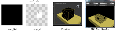
"d" and "Tf" interact in nonobvious ways, as shown below (there is no map_Kd on these).

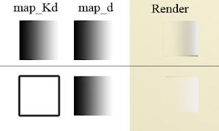
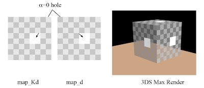
Finally, I've heard that some packages recognize map_d textures with an alpha channel and use that instead of the intensity, so that you can use "map_d file / map_Kd file" to get alpha cutouts. 3DS Max does not:
Transmission Holds Out Reflection


Transmission Holds Out Reflection
In 3DS Max, the reflected light is automatically reduced by the transmissive coefficient (this is analogous to partial coverage with a convention of NOT using premultiplied alpha). The experiment that I used to determine this is below. In it, the two cubes are rendered from directly above.

Conclusions: Alpha
Unfortunately, from these experiments, it appears that there is no way to do an "alpha cutout" in OBJ format that will be rendered correctly as partial coverage in 3DS Max. The lack of this is troubling; the best that one can do to fake it is apparently to:
- Ks = 0 0 0
- Specify a grayscale map_d, where 0 = hole and 1 = solid
- Do not premultiply coverage by map_Kd
I intend to support colored transmission with "Tf" and "map_Tf", and will accept that 3DS Max and other programs may ignore the color (but will at least maintain the average transmission).
Post Script: What about Blender?
Blender seems to completely ignore "Tf" and uses the alpha channel of the map_Kd for alpha cutouts.
Post a Comment for "Translucency in OBJ / MTL Files"
If you have something to say, please leave a message in the comments :)